

Manyug Enterprises has established itself as a leading innovator in Water Treatment Solutions. We specialize in delivering a comprehensive range of advanced water filtering systems tailored to meet the needs of Industrial, Commercial, and Residential clients.
Call Us : +91 9923204428
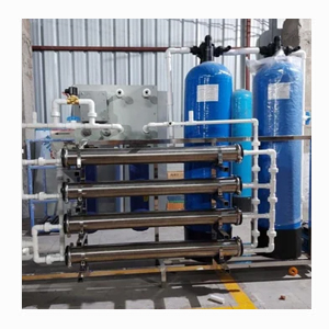


Manyug Enterprises is a water treatment plant manufacturers in Pune. We are reliable suppliers, exporters, traders and repairing services in Pune, serving industrial, commercial, and residential clients across Maharashtra. We design and build water treatment plants for a range of applications, including industrial process water, effluent treatment, sewage treatment, and high purity water systems. Capacity is taken from the daily volume and the hours the plant will run, then checked against a raw-water report for every source on the site. Filtration, softening, reverse osmosis, ultrafiltration and demineralisation are selected from that report. Effluent and sewage plants are a separate design.
Every plant we build is engineered around the customer's raw water quality, required capacity, and end use requirements, since there is no one size fits all system. Whether you need a compact RO plant for a small facility or a larger effluent treatment setup for an industrial unit, our team studies your water analysis report and application before recommending a configuration.
A water treatment plant changes raw water into water that meets a use specification. The use may be drinking, a phosphate or paint bath, boiler feed, cooling-tower make-up, or a rinse. The unit operations remove a named contaminant. They do not "purify" in the abstract.
Suspended solids and turbidity are removed by coagulation, if needed, and by a pressure sand or multimedia filter. Dissolved iron is oxidised to ferric hydroxide and filtered. Hardness, which is calcium and magnesium, is exchanged for sodium on a cation resin if scale, not salt, is the limit. Dissolved salts and silica pass a softener and a carbon filter unchanged. They are rejected by a polyamide reverse osmosis membrane, or exchanged on a demineralisation train if conductivity must go lower still.
A sewage plant is a biological plant for domestic waste. A typical inlet BOD is 200–350 mg/L. An effluent plant is a chemical and biological plant for process wastewater, often 500–10,000 mg/L COD depending on the industry. Manyug builds those too. They are not sized from a borewell TDS report, and they are not sold as a rinse or drinking plant.
| Parameter | Pune borewell, typical | After pretreatment | RO permeate | Design value | Failure if ignored |
|---|---|---|---|---|---|
| Sizing | Site m³/day | — | 500–50,000 LPH | Flow = m³/day ÷ hours | A 100 KLD plant built as 100 m³/h |
| Turbidity | 2–15 NTU | < 1 NTU | < 0.2 NTU | IS 10500 desirable 1 NTU | SDI rise, colloidal fouling |
| pH | 7.0–8.2 | 6.8–7.8 | 6.5–7.5 | Drinking 6.5–8.5 | Alkaline scale if concentrate pH is high |
| TDS | 600–1,800 mg/L | Unchanged | 30–120 mg/L | Drinking desirable 500 mg/L | Rinse spotting, tower scale |
| Hardness as CaCO₃ | 250–700 mg/L | < 50 mg/L if softened | < 10 mg/L | Desirable 200 mg/L | CaCO₃ scale on the tail element |
| Iron | 0.3–3.0 mg/L | < 0.1 mg/L | < 0.05 mg/L | 0.3 mg/L | Irreversible metal fouling |
| Silica as SiO₂ | 15–40 mg/L | Unchanged | 1–4 mg/L | Sets recovery | Silica scale, not removed by acid clean |
| Chloride | Often 50–400 mg/L | Unchanged | Low in permeate | Concentrate attacks SS 304 | Pitting of the wrong alloy |
| Free chlorine | Dosed for iron | Not detectable | — | Zero at polyamide | Membrane oxidation within days |
| SDI₁₅ | — | < 3, alarm at 5 | — | Pretreatment guarantee | Colloidal fouling within weeks |
| Element | — | — | 8040, 37–41 m² | Flux 18–25 L/m²·h | Flux above 25 blinds the surface |
| Pressure | — | — | 8–15 bar | Rises as water cools and elements age | Undersized pump in winter |
| Recovery | — | — | 60–75% | 80% only after projection | Scale at the last element |
| Rejection | — | — | 97–99.5% new | 90% is a fault | Quiet salt passage into the rinse |
| Energy | — | — | 0.8–1.6 kWh/m³ | No energy recovery at this size | Understated operating cost |
| Life | — | — | 2–3 years | Clean at +15% normalised ΔP | Early replacement |
| Filter, 5 m³/h | — | 10–15 m/h | — | Backwash 25–35 m/h, 10–15 min | Mud balling, turbidity breakthrough |
| Softener salt | — | 120–160 g/L resin | — | Hardness load sets bed volume | Hardness leakage |
| Metallurgy | — | FRP or lined MS | SS 316 permeate | No 304 on concentrate | Chloride pitting |
| Effluent reference | — | — | Not this plant | BOD 30, COD 250, TSS 100, oil 10 mg/L | WTP quoted against a consent limit |
Osmotic pressure is about 0.7 bar per 1,000 mg/L TDS. A 1,500 mg/L feed needs on the order of 10 bar before flux is useful, which is why the pump is specified at up to 15 bar with a variable-speed drive. Salt passage also rises as the element warms, so a guarantee written at 25 °C will not match a permeate sample taken at 35 °C unless it is temperature-corrected.
| Feature | What it controls | Site result |
|---|---|---|
| Two-source design | Worse of MIDC and borewell | No April fouling when the bore is opened |
| Oxidation tank ahead of sand | Ferrous iron | Iron held under 0.1 mg/L into the cartridge |
| Carbon after chlorine | Free chlorine | Polyamide layer stays intact |
| Antiscalant plus recovery cap | Silica and hardness in the concentrate | Tail element does not scale |
| 2:1 array | Cross-flow at the last element | Lower deposition than a single long vessel |
| Variable-speed pump | Feed TDS from about 300 to 1,400 mg/L | Stable permeate without a second skid |
| Duty split | Process versus domestic | RO power not spent on toilets |
| Reject to the effluent tank | 25–40% concentrate | No raw brine to the drain |
| Normalised data log | Flow, salt passage, ΔP | Clean at +15% ΔP, not on a calendar |
Problem. Equipment washing was on borewell water that a sand filter could not hold to the wash specification. Feed conductivity was 850 µS/cm, TDS 620 mg/L, hardness 480 mg/L as CaCO₃, and the plate count was 220 CFU/mL.
Solution. A 25 KLD plant, 1.6 m³/h at 16 hours, on the wash loop only. Multi-grade filter, ultrafiltration, two-pass reverse osmosis and UV on the permeate tank.
Result. Outlet conductivity was 2.1 µS/cm. That is wash water, not pharmacopoeial purified water.
| Parameter | Feed | Outlet |
|---|---|---|
| Conductivity | 850 µS/cm | 2.1 µS/cm |
| TDS | 620 mg/L | 8 mg/L |
| Hardness as CaCO₃ | 480 mg/L | < 5 mg/L |
| Plate count | 220 CFU/mL | < 10 CFU/mL |
Problem. Municipal water blended with a borewell was used for CNC coolant and component washing. Hardness was 540 mg/L, TDS 980 mg/L and turbidity 14 NTU. Wash nozzles were blocking.
Solution. A 15 KLD skid, 1.5 m³/h at 10 hours, on the coolant and wash lines only. Pressure sand filter, sodium softener and single-pass RO at about 70% recovery.
Result. Hardness fell to 12 mg/L and TDS to 40 mg/L. Tool life was not part of the guarantee.
| Parameter | Feed | Outlet |
|---|---|---|
| Hardness as CaCO₃ | 540 mg/L | 12 mg/L |
| TDS | 980 mg/L | 40 mg/L |
| Turbidity | 14 NTU | < 1 NTU |
Problem. Milk chilling, CIP and packaging needed low turbidity and no coliform. Monsoon borewell water was turbidity 22 NTU, iron 2.4 mg/L and total coliform 180 MPN/100 mL.
Solution. A 60 KLD plant, 3 m³/h at 20 hours, with no RO. Iron is oxidised, then coagulation, sand, carbon, UV and ozone.
Result. Turbidity was under 1 NTU, iron under 0.1 mg/L, and coliform was not detected. TDS did not change.
| Parameter | Feed | Outlet |
|---|---|---|
| Turbidity | 22 NTU | < 1 NTU |
| Iron | 2.4 mg/L | < 0.1 mg/L |
| Total coliform | 180 MPN/100 mL | not detected |
Problem. Baths were made up on borewell water at hardness 610 mg/L, TDS 1,050 mg/L and iron 1.9 mg/L. Shade was moving between batches.
Solution. A 50 KLD plant, 2.5 m³/h at 20 hours. Iron is filtered, two softeners run in swing service, and RO follows at 65% recovery.
Result. Hardness was 8 mg/L, TDS 35 mg/L and iron under 0.05 mg/L. Shade rejection was not offered as a water-plant result.
| Parameter | Feed | Outlet |
|---|---|---|
| Hardness as CaCO₃ | 610 mg/L | 8 mg/L |
| TDS | 1,050 mg/L | 35 mg/L |
| Iron | 1.9 mg/L | < 0.05 mg/L |
Manyug Enterprises is a leading Water Treatment Plant Manufacturers in Pune. We are trusted Suppliers, Dealers and wholesalers in Pune. A Pune water treatment plant is sized on every source the site can run, then built only for the contaminants that source contains. Filtration and oxidation take turbidity and iron. Softening takes hardness and does not take TDS. RO takes TDS and silica at 8–15 bar and 60–75% recovery, with chlorine absent and SDI under 3. Effluent limits are a different plant. Contact Now!